Learning Journal

Planning
I know what is expected of my rig, in the research section I looked at the current example animation of the product in use. I also found this video of the product in use within the industry, this will help when thinking about what can and cannot be seen during the motions of the product.
Source: Geith YouTube Channel
https://www.youtube.com/watch?v=IWXOMcmyd90
I'm thinking about this from two perspectives;
-
Driver/Operator PoV - There are sections of the internals that would be seen.
-
Marketing Camera PoV - This is down to my discretion so I'll identify if any geometry can be eliminated
Right is an exert under the heading Planning the Actions from "Rigging Guideline for the Artist: What's Important for a Good Rig?" a Plural Sight article

Right is a collection of the six tutorial and lecture videos that I used as my reference and guidance throughout this project.
At several points during the Wire Parameter process I had Skype calls with my tutor (Lee) who suggested Paul Neale.
Lee explained the basics of Wire Parameters, helped me with the issues before I'd learnt about Freezing Transform and Rotation, he also explained what resetting the Xform for geometry was for.


Testing and Development

Blog Spot
I started with creating the base rig.
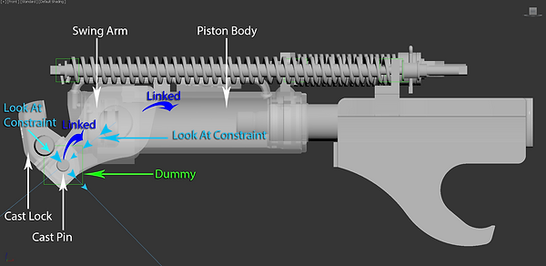
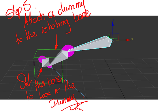
I started by creating a simple test rig using bones and for the hydraulic cylinder I added a dummy at each pivot to use a Look At constraint on the two bones representing each element of the the hydraulic cylinder.
The image to the left shows the layout of the bones and dummies.
The coloured bones (Blue & Orange) match the dummies and the arrows show the direction of the Look At constraint.
I created the simple test rig for the internals in a similar way. The springs are Dynamic Objects within Max the top and bottom of the spring are bound to separate dummies, this allows me to compress the springs during the animation sequence by linking one of the dummies to the moving bone.
Click the image below for fullscreen
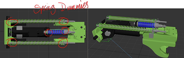
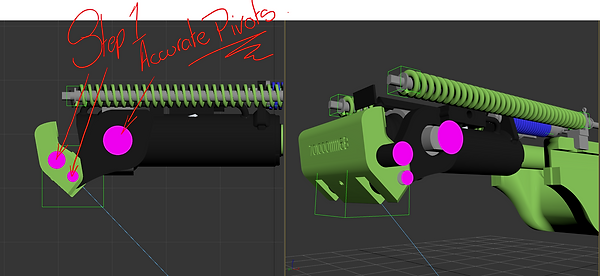

Although this is a simple test rig I may go on to develop it from this file, to make sure the rig moves correctly the pivots must be set accurately. I did this by creating Spline Circles in place of the pivots, they are all labelled and coloured pink to make it easier for me to locate and snap geometry, bones and dummies to.
(Image Left)
To get a feel for what I was trying to create I linked the the cast pin to the swing arm which was linked to the piston body.
It's never advised to use the geometry as part of the rig, this was a simulation of the action I wanted my rig to achieve.
(Image Right)
Blog Spot
My early test rigs highlighted issues which I demonstrate in this blog, following guidance from my tutor I looked into Wire Parameters
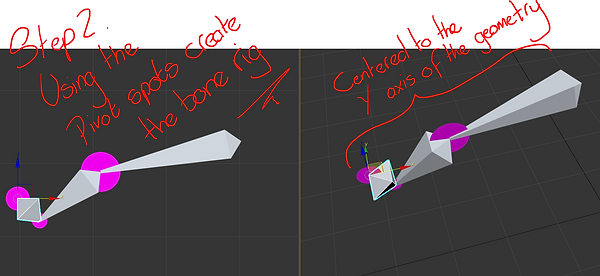
Here is how I've developed my rig with bones, I used the pivots created earlier to snap the bones too.
Freeze the bones rotation and transform by holding the Alt key a right clicking the bone.
Follow the quad menu as illustrated in the image (Right)

Here is a video that shows what can happen if the transform and rotating isn't frozen.
This can happen to any element within a scene, we generally don't notice it until we try to animate, add a constraint, etc.

Remembering to check the orientation of the bones from different view ports or angles.
Click the image (Left) for fullscreen. If the bones are positioned correctly they could perform in strange ways later on.
Now I'm placing a Dummy in position of the Cast Pin pivot and Linking it to the rotating bone (Middle)
Next I add a Look At constraint to the Cast Lock bone (Far Left) this is set to look at the Dummy
When the Piston Body Bone (Far Right) is moved right it will pull on the Swing Arm Bone (Middle) the Dummy will follow the rotation of the Swing Arm and the Cast Lock Bone will rotate at it's pivot to Look At the Dummy. Simulating the unlocking of the mechanism.

It is always a good idea to keep scenes tidy, before long you will have plenty of objects and elements going on and when working in the industry it's always who can achieve the desired outcome the cheapest and the quickest.
In the images below I show how to apply the Wire Parameter constraint, starting by right clicking the initial bone. (Click image for fullscreen)
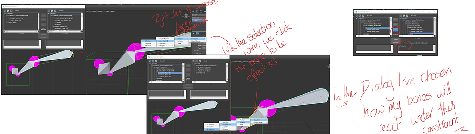


Once the Wire Parameter has been set the Dialog window appears.
This allows the user to set several parameters, first chose which way (or both) you want the parameter to effect.
In my project I want the 1st bone (Piston) to act as the master and effect the 2nd bone (Swing Arm), making the 2nd bone the slave.
Under each tree is the expression box, this gives the user the ability to control how much effect the parameters have.
This took a little bit of trial and error. The images left show the sequence I went through to find the best expression to suit my project requirements.
The initial expression was
-X_Position-5.15
-X_Position tells the slave bone to move negatively (In the opposite direction)
-5.15 this reduces the rotation based on the movement of the master bone
This initial expression meant the slave bone would reach it's desired end position before the slave bone reached it's desired end position.
The final image (Above) shows the initial expression against my final expression of -X_Position/10
In the final expression I divided the movement of the master bone by 10 to reduce the rotation of the slave bone.
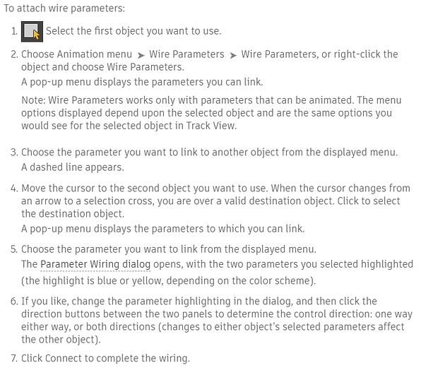
Right is the Autodesk documentation for how to create Wire Parameters.
I created this video (Right) during my research and development stage of using Wire Parameters.
I was having problems due to not Freezing Transform and Rotation
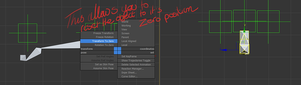
Earlier I talked about the importance of Freezing Transform and Rotation, this allows the user to reset the Transform or Rotation to Zero at anytime. This can be very helpful when you are testing and need a clean setup to go back to, this will reduce undesired results later on down the line.
I had started with creating the internal rig because I felt this was going to be the area I found most difficult. Down the line while researching Wire Parameters I read this (Below)

All part of the learning process, so happy with the internal rig setup I started to look at the Hierarchy of the whole rig.
Building the final piece

Blog Spot
Here is a blog post I wrote with regards to getting accurate pivots in preparation for creating the geometry ready to skin the rig too.
During the above post I explained some sections that required the assistance of images, due to the nature of Wix's blog post those images can't be viewed in fullscreen. Below are all the images that can be viewed in fullscreen, their respective write-ups are within the fullscreen view.


Blog Spot
With the pivots accurately setup I created the complete rig, I made a slight tweak when applying the Wire Parameter, I adjusted the expression to -X_Position/9
This wouldn't have been noticed in the animation but I like things to be just right.
Now that the rig is complete I'll move on to creating the clean geometry ready for Skinning and Key Framing the animation ready for rendering.

Blog Spot
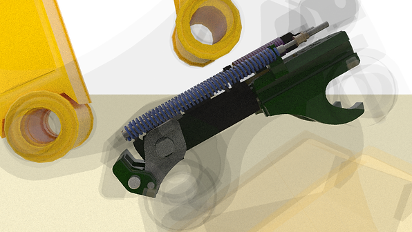
I tried using the mesh, more through anticipation of what the animation sequence could look like.
This didn't go well, 600k polygons was to much for Max to handle in an animation.
I touched on creating the new geometry using the original mesh as a guide. Below I've created a gallery for the major sections I worked on.
Dan took care of the larger sections and I created the internal components, mainly because I knew what I could chop out without it affecting the animation at the end. Essentially I wanted to trim the poly count to a max of 60k.


After the massive polygon diet I didn't have any trouble Key Framing the animation and didn't need to use the Point Cash modifier.
Rendering
The final video could be shown on a large screen at a show, so I was unsure about how big I should be rendering out the images. I settle on 1920x1080 and the test frames came out fine.

To achieve this I chose to use V-ray render engine and materials.
The materials are nothing special, I wanted a clean production look for the final output rather than a used or even newly manufactured machine.
I planned to take the images into After Effects to add some post-production SFX before rendering the final video format as an AVI. This is also the best quality but suffers from the least compression, something I felt wouldn't be an issue with such a short video length and would look better on larger screens such as in shows.
This has been my first V-ray production render, although I've played with it in the past it's never been with a serious want to understand how to correctly light a scene, setup cameras and customise render settings.
Here is how I've light my scene and why:

Two Vray Lights set as Plane, with the same settings
Third Vray Lights set as Plane, set with a lower multiplier than the two behind the camera
Fourth Vray Light set as Dome, this will help to eliminate shadows on the product during the animation.
Vray Plane to create an infinite plane floor to cast shadows on to.

Left is the properties panel for the two lights behind the camera.
I Alterted the size of the plan to cast more light. So as not to effect the colours of the materials I use Color mode and set it to White.
I was happy with a multiplier of 1.2

Left is the properties panel for the third light plane.
I Altered the size of the plan to cast more light. Again using Color mode set to White.
I kept the multiplier default of 1.0

Left is the properties panel for the final light to help eliminate any shadows during the animation.
Again using Color mode and set it to White for consistency.
I was happy with the default multiplier.

I had tried to use a HDRI map in the Environment panel for a background, this didn't yield the best results with the way I'd animated the opacity of the material throughout the sequence. As seen below.

Left: image rendered with HDRI map with the settings to not render as background. The problem occurs through the transparency of the coupler body material, you can see the HDRI map rendered behind.
Click image for fullscreen
Although I would have liked the time to investigate a work around because the colours are sharper.
Right: image rendered without HDRI map, notice the graining on the floor.
Click image for fullscreen
This was the result of the render settings, as default Vray Image Sampler is set to Progressive.
This allocates an amount of time per frame as an average across the whole length of the sequence. So during frames where the render is heavier the render quality isn't as crisp. This is mainly an issue because it lowers the overall quality of the animation and the use of higher quality post SFX would highlight this even more.
Changing to Bucket Image Sampling renders each frame to the set quality by allowing for the whole frame rendering time. This makes the rending time longer but the final images will be higher quality.

Below is the final rendered animation sequence.
There is an issue I hadn't forgotten to correct, the bucket is set to rotate 180 degrees, because the bucket can be rotated clockwise or anti-clockwise I should have rotated 170 degrees and then key framed the further 10 degrees correspondingly to determine a set rotation path.
At 15 seconds into animation the bucket flips back 180 degrees, an issue known as Gimbal lock. This is caused when two axis are are perpendicular to the remaining axis. The image GIF gives a clear example of Gimbal Lock. This caused a problem when rendering, I check the first set of renders to see if the problem occurred then. The image below shows the final rendered frame where the bucket is facing the correct way.
Gimbal Lock Example GIF
There is more that I would have liked to do with the Post-Production SFX but I didn't allow the time for issues with the rendering dropping out so often.
360 Degree Product Tour
Part two of my brief is to create a product tour in UE4.
I'm going to use a downloaded model from Turbo Squid by Henry600. The model is 134,000 polygons and came rigged, I'll start with trimming down the polycount ready for creating my own rig.
I want to practice what I've learnt with rigging so far, I'll be adding the coupler (minus internals) and bucket instead of the of the bucket and attachment rig it came with.

Blog Spot
I talk about what I want to do with regards to optimising this model for UE4.
Also looked into the comparison between 3Ds Max Dummies and UE4 Sockets
In the above blog post I showed a picture taken from a forum discussing using Max Dummies/Points as Sockets in UE4, the image below can be viewed in fullscreen.

The video below shows how I stripped polygons from the bucket.

Blog Spot
Here is the process I took for preparing the mesh ready for rigging and skinning.
Reflective Analysis
What happened? -
To summarise, I set out to complete a two part brief, first a product demo animation and second a 360° product tour in UE4.
The first part of the brief was to replicate a demo video but give it a fresh and more professional look. I created a replica mesh, rigged, skinned and key framed the animation in 3Ds Max, rendering the sequence as TIF files in Vray to bring into After Effects add post-production SFX and finally render a AVI video format.
Second part of the brief was to create an interactive product tour of an excavator in Unreal Engine 4 (UE4). The user would be able to see the product in action with hotspot information for the user. I did primary research while completing the first part of my brief in the form of the rigging and skinning, also I contacted two primary sources.
First Darual Solutions in India who have created a product tour package using the UE4 software, I was able to contact the lead designer of the project. He was very helpful in answering the questions he could, the company offered me the source file for a fee, and along with the source file they were willing to provide support.
Second was Frederick Church of Bare Bone Games, he has a project in development; an ocean exploration game, where the user has the ability to explore with user of robotic arms. Frederick’s primary research was to start with a 6 bar linkage excavator arm, he was extremely informative and we continue to talk about our projects.
I planned to have at least a prototype demo created, at present I’m rigging the excavator for Unreal. I will see this project through to completion following submitting.
Feelings –
I’m extremely pleased, although I wasn’t able to manage the whole brief; the fact that I took the first part from concept to industry standard completion.
The ability to manage my time across all the modules at the beginning of 2018 was an achievement in itself. This has been my most rewarding year, but I’ve proven to myself that I can be a Freelance Artist, and I can manage myself, time, personal growth and development.
I’m proud of what I have achieved and that I see the directions to improve on. I feel the connections I’ve made in the industry already will grow and I’ll keep building on them.
Evaluation & Analysis –
Looking back over this project in particular, I identified an area I could push hard in. Somewhere I wouldn’t have first thought of; animation, but it played to my strengths in the technical challenge of creating a well designed rig to not only for me, but for anyone else with a basic knowledge to manipulate (hypothetically).
There are areas I know that will be faster every time I use them, the hard surface modelling is something I get great joy from. The rigging is enjoyable but for different reason; it enjoy the challenge but I’m driven by being able to see it breath with life once animated.
I’d not touched on rendering much up until this my final major; I’ve downloaded the Vray Beta for UE4 and look forward to putting that through its paces very soon.
Conclusion –
Going forward with what I’ve learnt I’ll continue to learn Vray, UE4 to complete the second part of my FMP brief.
I’ll continue to build on connections made, I made a bold statement showing what I could do and I believe in stepping out of the comfort zone to get to where we ultimately want to go.
It takes nothing to write an email to a fellow artist or studio, so why not take it that step further and pick up the phone a day later to introduce you personally. Get familiar with this step often enough and you’ll soon be calm enough to ask to visit in person, first impressions count! It’s here where you’ll be able to find out if there is an opportunity for you to gently place you proverbial foot in the door, ask questions that may unearth clues to what could be in the pipeline. Find a nugget, a whiff of what is round the corner for them, question gently about what they may do for such a brief, do they have a separate department, how many artists, etc.
Action Plan –
Continue the Udemey course I purchased to get me back on track in February.
Finish the product tour project.
Complete model, render and rig for a car.
Start looking into VR in UE4.
That should keep me busy until Christmas